specification

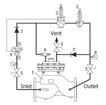
| number | Components |
| One | BALEM 130 (Robocon Valve) |
| 2 | Pressure Reducing Pilot Valve |
| 3 | Pressure Sustaining Pilot Valve |
| 4 | Needle & Strainer |
| 5 | Cock Valve |
| 6 | Flow Controller |
| 7 | Check Valve |
| 8 | pressure gauge |

| Pressure Relief Valve Selection Guide |
| If there is no intermediate demand A (in the case of intuition with a large elevation difference) |
If the intermediate demand is A (sometimes if the demand is singular to A) |
In the case of a block system |
|
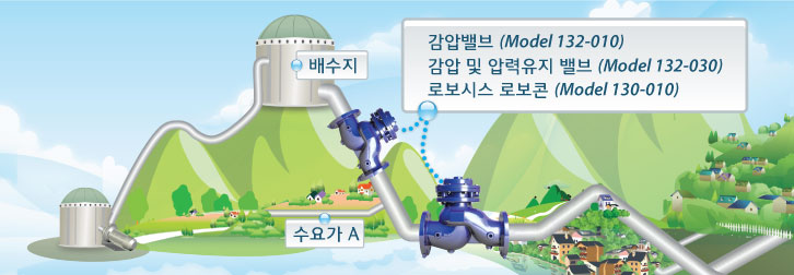
If the supply pipe is long and the height difference is large, it is the safest and most efficient to install a general pressure reducing valve (model 132-010) in the middle.
However, if there is a possibility that there is a possibility of generating electricity in a nearby area in the future, it is recommended to consider a pressure reducing and pressure maintaining valve (Model 132-030) with a pressure maintaining function at the front end. ※ Pressure reducing valve (Model 132-010)
|
If there is a demand in the middle and a lot of water is used in the sub-system, the area where there is a possibility of water outage at a high-altitude customer is a pressure reducing and pressure maintaining valve with a pressure maintaining function at the front end rather than a general pressure reducing valve (Model 132- 030) is the safest and most efficient.
※ Pressure reducing and pressure maintaining valve
(Model 132-030)
|
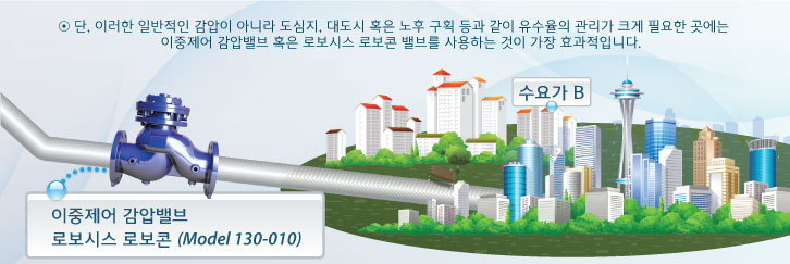
When water is systematically supplied by compartmentalizing (blocking) the supply area, it is the safest and most efficient to install the Robosys Robocon valve (model 130-010). It can be stably added to an already operated system, and if a control system is required, the BALEM SCADA System is provided.
※ Robosys Robocon
(Model 130-010)
|
| If there is no median demand A | bidirectional control | ||
| Built-in battery | electronic | Real-time flow detection | |
| ㆍBuilt-in battery that can be used for 5 years ㆍStable supply of water to the secondary side by dividing high-pressure and low-pressure time zones through time setting |
ㆍRequires external power supply ㆍ Section can be changed without limitation by external power control |
ㆍFully mechanical operation ㆍ Automatically change section by sensing actual flow ㆍNo limit on number of changes |
ㆍPrecise real-time bidirectional control by selecting the most efficient pressure for each time zone |
| ※ Time setting double control pressure reducing valve (Model 132-060) |
※ Solenoid type double control pressure reducing valve (Model 132-070) |
※ Flow-linked double control pressure reducing valve (Model 132-080) |
※ Robosys Robocon (Model 130-010) |

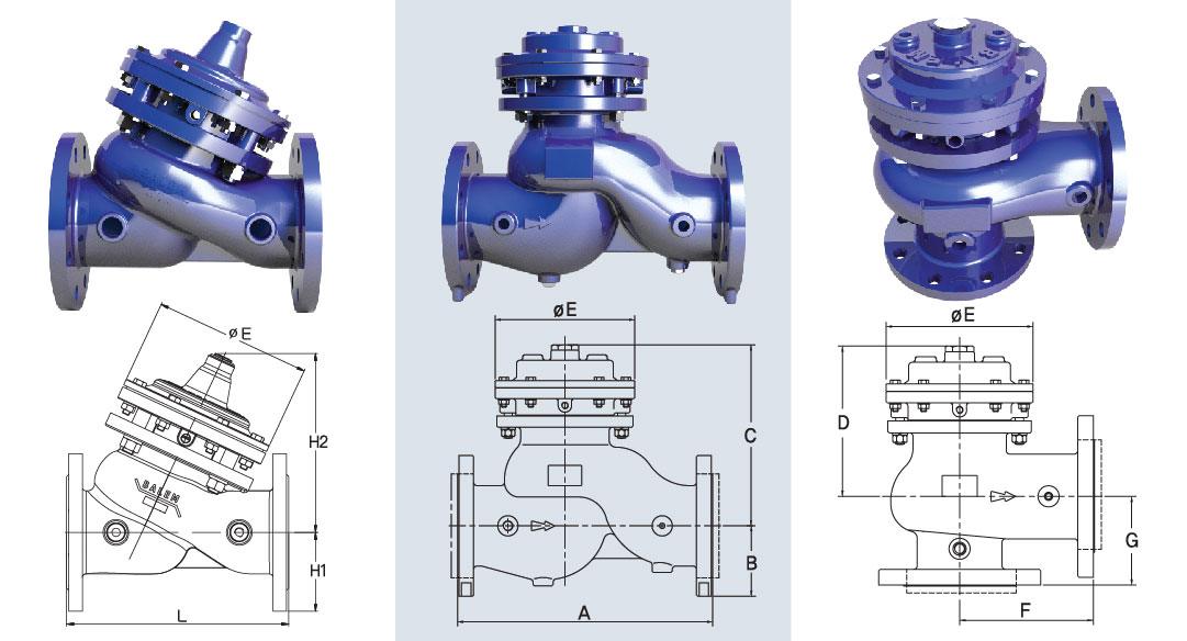
| Y-type Globe type flange type | Up-right Globe Flanged Type | Angle type flange type |
▼ Y-type Globe type valve size (mm)
| valve size | 50 | 65 | 80 | 100 | 125 | 150 | 200 | 250 | 300 | 350 | 400 | 500 | 600 | 700 | 800 | 900 | 1000 |
| L | 230 | 290 | 310 | 350 | 400 | 480 | 600 | 610 | 700 | 730 | 910 | 1010 | 1200 | 1400 | 1480 | 1650 | 1800 |
| H1 | 78 | 88 | 100 | 110 | 125 | 143 | 175 | 205 | 230 | 265 | 300 | 380 | 420 | 500 | 565 | 590 | 640 |
| H2 | 188 | 211 | 236 | 270 | 333 | 353 | 461 | 519 | 615 | 629 | 753 | 893 | 1030 | 1255 | 1412 | 1461 | 1584 |
| ØE | 135 | 154 | 180 | 220 | 260 | 305 | 380 | 455 | 545 | 545 | 705 | 794 | 934 | 1160 | 1215 | 1315 | 1400 |
▼ Up-right Globe & Angle type valve size (mm)
| valve size | 50 | 80 | 100 | 150 | 200 | 250 | 300 |
| A | 238 | 305 | 381 | 508 | 645 | 756 | 864 |
| B | 78 | 93 | 105 | 140 | 165 | 200 | 223 |
| Cmax | 200 | 240 | 275 | 375 | 470 | 535 | 625 |
| Dmax | 157 | 179 | 206 | 284 | 360 | 420 | 465 |
| ØE | 140 | 165 | 208 | 326 | 408 | 497 | 562 |
| F | 119 | 152 | 191 | 254 | 322 | 378 | 432 |
| G | 83 | 102 | 127 | 152 | 203 | 219 | 349 |
※ The tolerance of the inter-face distance dimensions (A, F, L) follows the tolerance standard in <Table 11> of KS B ISO 5752.

| Robocon series | |||
| shape and size |
Up-right Globe / Angle Type
|
Y-Type Globe
|
|
|
50 to 300A
|
50 to 1000A
|
||
| working pressure | 10kgf/cm2, 16kgf/cm2, 20kgf/cm2, 25kgf/cm2 | ||
| Connection standard | Manufactured according to customer requirements | ||
| used fluid | Water / Diesel (Optional) Contact the head office / Fluid temperature: 0°C ~ 80°C | ||

| Components | material type | ||
| Standard | Optional | ||
| 50A~350A | 400A~1000A | ||
| Body & Cover & Disc | Ductile Iron | Cast Steel | SSC 13 |
| diaphragm washer | Ductile Iron | Cast Steel | SSC 13 |
| Cover Plugs & Bearings | SSC 13 | ||
| Shaft & Seat | STS 304 | ||
| diaphragm | NR / CR / NBR | ||
| disc seal | NR / CR / NBR | ||
※ Epoxy coating of NSF/ANSI Standard 61 is standard.

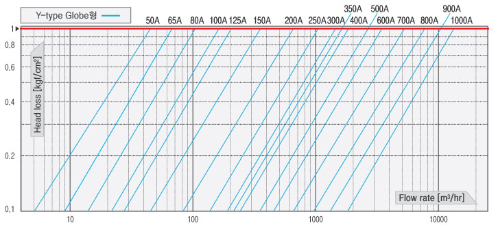
▼ Y-type Globe type flow chart
| standard | mm | 50 | 65 | 80 | 100 | 125 | 150 | 200 | 250 | 300 | 350 | 400 | 500 | 600 | 700 | 800 | 900 | 1000 | |
| inch | 2 | 2 1/2 ” _ _ | 3 | 4 | 5 | 6 | 8 | 10 | 12 | 14 | 16 | 20 | 24 | 28 | 32 | 36 | 40 | ||
| flow coefficient | Y-Type Globe | Kv | 48 | 72 | 102 | 178 | 221 | 385 | 672 | 973 | 1382 | 1610 | 1834 | 2863 | 3816 | 5311 | 7508 | 9130 | 13085 |
| Cv | 56 | 84 | 119 | 208 | 258 | 450 | 784 | 1137 | 1614 | 1881 | 2142 | 3344 | 4457 | 6203 | 8769 | 10664 | 15283 | ||
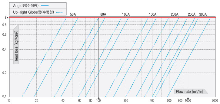
▼ Up-right Globe & Angle Flow Chart
| standard | mm | 50 | 80 | 100 | 150 | 200 | 250 | 300 | |
| inch | 2 | 3 | 4 | 6 | 8 | 10 | 12 | ||
| flow coefficient | Globe Type | Kv | 46 | 97 | 177 | 361 | 618 | 970 | 1378 |
| Cv | 54 | 113 | 207 | 422 | 722 | 1133 | 1610 | ||
| Angle Type | Kv | 57 | 121 | 220 | 459 | 779 | 1251 | 1764 | |
| Cv | 67 | 141 | 257 | 536 | 910 | 1461 | 2060 | ||
| Flow coefficient Kv or Cv = Q/√ΔP, Cv = 1.168Kv |
| Kv: Flow rate per hour Q (㎥/hr) at differential pressure 1 (kgf/㎠) |
| Cv: Flow per minute Q (Gal/min) at differential pressure 1 (PSI) |
| ΔP : pressure difference between both ends of the valve (kgf/cm2 or PSI) |

|
||||||||||||||||||||||||||||||||||||||||