![]()

Pressure reducing valve, pressure reducing and pressure maintaining valve to solve the discharged water, time setting to maximize the flow rate, double control pressure reducing valve, flow interlocking double control pressure reducing valve, Robosys Robocon valve for real-time monitoring/control
installed in the drain pipe
The method of commissioning the valve is as follows.:
![]()
– Pressure reducing valve: Regardless of the pressure fluctuation on the primary side and the flow rate on the secondary side,
A valve that maintains a constant pressure.
After installing the pressure reducing valve as shown in the standard piping diagram below, follow the trial operation guide
Proceed with commissioning.
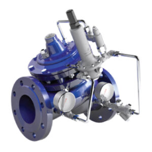
<Reducing valve>
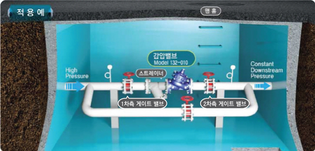
<Standard piping diagram for pressure reducing valve>
![]()
 +
+
| step | explanation |
| Step. One | 1, 2Completely shut off the secondary gate valve and bypass piping. |
| Step. 2 | OneFully open the vehicle side gate valve to fill the pressure reducing valve with water.. |
| Step. 3 | 2car side gate valve 10-20%only by opening 2Fill the car side with water.. |
| Step. 4 | Fudan Ito side(or fire hydrant, acceptor)slightly open, Let the water flow through the pressure reducing valve. |
| Step. 5 | Pressure Reducing Pilot Valve (2) open the top cap, Loosen the nut of the adjusting screw. |
| Step. 6 | installed at the rear of the pressure reducing valve 2looking at the pressure gauge, Adjust the pressure reducing pilot adjusting screw to 2Set the outlet pressure. (counterclockwise to decrease pressure, Slowly turn clockwise to increase pressure.) [If there are no special requirements when shipping the product, basic 3kgf/cm2 state] |
| Step. 7 | After completion of decompression setting, After confirming that it is operating normally, close the nut of the adjusting screw and turn on the pressure reducing pilot.(2) close the top cap. |
| Step. 8 | 2Slowly fully open the vehicle side gate valve. |
| Step. 9 | Fudan Ito side(or fire hydrant, acceptor)shut off slowly. |
| ※ forced open After shutting off the Cock Valve (4-1, 4-2), slowly open the Cock Valve (4-3). (At this time, water comes out of the Cock Valve (4-3), so open it slowly. And when the water in the main valve cover runs out, no more water comes out.) |
|
| ※ force block Open the Cock Valve (4-1) and close the Cock Valve (4-3). Then slowly shut off the Cock Valve (4-2). |
|
| ※ During valve use(If water is flowing)When resetting the pressure to, Step. 5 →Step. 6 → Step.7 run. | |
※ Caution : When the secondary side gate valve is opened rapidly, the secondary side pipe may be damaged, and it must be opened slowly
to prevent dynamic pressure .
※ Caution : If the piping needs to be cut off due to damage to the piping connected to the secondary side or additional construction, the
secondary gate valve must be completely shut off.
When re-watering, re-test run as above.
※ – Pressure reducing valve selection guide (Link) –
※ – Pressure reducing valve maintenance manual (link) –
![]()
– Pressure reducing and pressure maintaining valve: maintains the secondary side at the set low pressure,
It is also a valve that maintains the inlet pressure at the set pressure.
After installing the pressure reducing and pressure maintaining valves as shown in the standard piping diagram below,
Proceed with commissioning according to the commissioning guide.
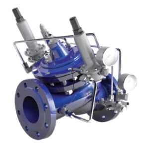
<Pressure Relief and Pressure Retention Valve>
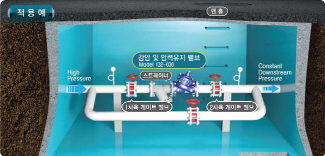
<Standard piping diagram for pressure reducing and pressure holding valves>
![]()
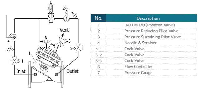
| step | explanation |
| Step. One | 1, 2Completely shut off the secondary gate valve and bypass piping. |
| Step. 2 | OneFully open the secondary side gate valve to fill water up to the pressure reducing and maintaining pressure valves.. |
| Step. 3 | 2car side gate valve 10-20%only by opening 2Fill the car side with water.. |
| Step. 4 | Fudan Ito side(or fire hydrant, acceptor)slightly open, Allow water to flow through the pressure reducing and maintaining pressure valves. |
| Step. 5 | Pressure Reducing Pilot Valve(2) open the top cap, Loosen the nut of the adjusting screw. |
| Step. 6 | Installed at the rear of the pressure reducing and pressure maintaining valve 2looking at the pressure gauge, Adjust the adjusting screw 2Set the outlet pressure. (counterclockwise to decrease pressure, Slowly turn clockwise to increase pressure.) [If there are no special requirements when shipping the product, basic 3kgf/cm2 state] |
| Step. 7 | After completion of decompression setting, After confirming that it is operating normally, close the nut of the adjusting screw and turn on the pressure reducing pilot.(2) close the top cap. |
| Step. 8 | 2Slowly fully open the vehicle side gate valve. |
| Step. 9 | Fudan Ito side(or fire hydrant, acceptor)while slowly opening, OneAdjust the pressure enough to maintain the pressure on the car side.. |
| Step. 10 | Pressure Sustaining Pilot Valve)(3) open the cap, Loosen the nut of the adjusting screw. |
| Step. 11 | Installed in front of pressure reducing and pressure maintaining valve Onelooking at the pressure gauge, Adjust the adjusting screw OneSet the outlet pressure. (counterclockwise to decrease pressure, Slowly turn clockwise to increase pressure.) [If there are no special requirements when shipping the product, Default 3kgf/cm2 condition] |
| Step. 12 | After completion of pressure maintenance setting, After confirming that it operates normally, close the nut of the adjusting screw and turn on the Pressure Sustaining Pilot Valve.)(3) close the top cap. |
| Step. 13 | Fudan Ito side(or fire hydrant, acceptor)shut off slowly. |
| ※ forced open After shutting off the Cock Valve (5-1, 5-2), slowly open the Cock Valve (5-3). (At this time, water comes out of the Cock Valve (5-3), so open it slowly. And when the water in the main valve cover runs out, no more water should come out.) |
|
| ※ force block Open Cock Valve (5-1) and close Cock Valve (5-3). After that, slowly shut off the Cock Valve (5-2). |
|
| ※ During valve use(If water is flowing)When resetting the decompression pressure to, Step. 5 → Step. 6 → Step. 7 run. ※ During valve use(high flow rate OneWhen the downside pressure is low)When resetting the pressure holding pressure to, Step. 10 → Step. 11 run. |
|
※ Caution : When the secondary side gate valve is opened rapidly, the secondary side pipe may be damaged, and it must be opened slowly
to prevent dynamic pressure .
※ Caution : If the piping needs to be cut off due to damage to the piping connected to the secondary side or additional construction, the
secondary gate valve must be completely shut off.
When re-watering, re-test run as above.
※ – Causes and solutions to the problem of non-exhaust water (link) –
※ – Operating principle and setting method of pressure reducing and pressure holding valve (Link) –
※ – Pressure Relief and Pressure Retaining Valve Maintenance Instructions (Link) –
![]()
– Flow-linked dual control pressure reducing valve : This valve provides high pressure when the flow rate is high
and low pressure when the flow rate is low, such as late at night, and
automatically changes the supply pressure in response to the actual flow rate to increase the flow rate.
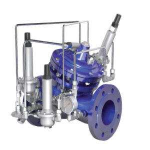
<Flow-linked double control pressure reducing valve>
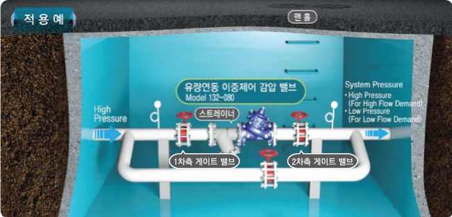
<Standard piping diagram for flow-linked dual control pressure reducing valve>
![]()
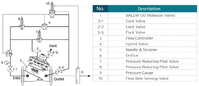
| step | explanation |
| Step. One | 1, 2Completely shut off the secondary gate valve and bypass piping. |
| Step. 2 | OneFully open the vehicle side gate valve to fill the pressure reducing valve with water.. |
| Step. 3 | 2car side gate valve 10-20%only by opening 2Fill the car side with water.. |
| Step. 4 | Fudan Ito side(or fire hydrant, acceptor)slightly open, Let the water flow through the pressure reducing valve. |
| Step. 5 | Pressure Reducing Pilot Valve(8) open the top cap, Loosen the nut of the adjusting screw. |
| Step. 6 | Fully loosen the high pressure pilot adjustment screw by turning it counterclockwise.. |
| Step. 7 | Pressure Reducing Pilot Valve(7) open the top cap, Loosen the nut of the adjusting screw. |
| Step. 8 | Installed at the rear of the flow-linked double control pressure reducing valve 2looking at the pressure gauge, Adjust the low pressure pilot adjusting screw to 2Set the outlet pressure. (counterclockwise to decrease pressure, Slowly turn clockwise to increase pressure.) [When the product is shipped, Unless otherwise required, basic 3kgf/cm2 state] |
| Step. 9 | After completing the low pressure setting, Tighten the nut of the adjusting screw and turn on the Pressure Reducing Pilot Valve (low pressure pilot).(7) close the top cap. |
| Step. 10 | When setting high pressure, Flow Rate Sensing Valve(10) open the top cap, Loosen the nut of the adjusting screw and completely loosen the adjusting screw.. |
| Step. 11 | Pressure Reducing Pilot Valve(8) open the top cap, Loosen the nut of the adjusting screw. |
| Step. 12 | Installed at the rear of the flow-linked double control pressure reducing valve 2looking at the pressure gauge, Adjust the high pressure pilot adjusting screw to 2Set the side pressure. (counterclockwise to decrease pressure, Slowly turn clockwise to increase pressure.) [When the product is shipped, Unless otherwise required, basic 4kgf/cm2 state] |
| Step. 13 | After completion of high pressure setting, After confirming that it operates normally, close the nut of the adjusting screw and turn on the Pressure Reducing Pilot Valve.(8) close the top cap. |
| Step. 14 | 2Slowly fully open the vehicle side gate valve. |
| Step. 15 | looking at the flow meter, Fudan Ito side(or fire hydrant, acceptor)open the high pressure·Set the desired flow rate at the time of low pressure switching.. |
| Step. 16 | Installed at the rear of the flow-linked double control pressure reducing valve 2looking at the pressure gauge, 2car side pressure Step. 6 Flow Rate Sensing Valve (Flow Sensing Pilot) until it changes to the low pressure set in(10)Slowly turn the adjusting screw clockwise to set the flow rate at the time of switching.. |
| Step. 17 | After completion of flow setting, After checking that it is operating normally, close the nut of the adjusting screw and turn on the Flow Rate Sensing Valve (flow detection pilot).(10) close the top cap. |
| Step. 18 | Fudan Ito side(or fire hydrant, acceptor)shut off slowly. |
| ※ forced open After shutting off the Cock Valves (2-1, 2-2), slowly open the Cock Valves (2-3). (At this time, water comes out of the Cock Valve (2-3), so open it slowly. And when the water in the main valve cover runs out, no more water should come out.) |
|
| ※ force block Open the Cock Valve (2-1) and close the Cock Valve (2-3). Then slowly shut off the Cock Valve (2-2). |
|
| ※ During valve use(If water is flowing)When resetting the low pressure to, Step. 5 → Step. 6 → Step. 7 → Step. 8 → Step. 9run. ※ During valve use(If water is flowing)When resetting the high pressure to, Step. 10 → Step. 11 → Step. 12 → Step. 13 run. |
|
– Flow Interlocking Dual Control Pressure Reducing Valve Maintenance Manual (Link) –
![]()
–Robosys Robocon : For efficient water resource management and maximization of
flow rate, pressure control and flow control used in various water piping systems are possible, and
through the built-in analog signal input port and pulse signal input port
It is possible to collect and store various information of the piping system,
It is a valve that can monitor/control the current status of the piping system in real time through the communication port.

<Robosys Robocon>
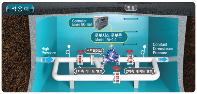
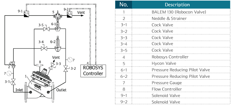
<Robosys Robocon standard piping diagram>
| step | explanation | |
| Step. One | 1, 2Completely shut off the secondary gate valve and bypass piping. | |
| Step. 2 | OneFully open the vehicle side gate valve to fill the pressure reducing valve with water.. | |
| Step. 3 | 2car side gate valve 10-20%only by opening 2Fill the car side with water.. | |
| Step. 4 | Fudan Ito side(or fire hydrant, acceptor)slightly open, Let the water flow through the pressure reducing valve. | |
| Step. 5 | Pressure Reducing Pilot Valve(6-2) cock valve on the side of the pipe(3-4)open the, Remote Control Decompression Pilot(6-1) cock valve on the side of the pipe(3-5)to block. | |
| Step. 6 | 2Slowly fully open the vehicle side gate valve. | |
| Step. 7 | Pressure Reducing Pilot Valve)(6-2)open the cap on top of, Loosen the nut of the adjusting screw. | |
| Step. 8 | Installed at the rear end of Robosys Robocon 2looking at the pressure gauge, Adjust the adjusting screw to lower the target pressure (Minimum holding pressure) 2Set the side pressure. (counterclockwise to decrease pressure, Slowly turn clockwise to increase pressure.) [When the product is shipped, Unless otherwise required, basic 3kgf/cm2 state] |
|
| Step. 9 | After completion of decompression setting, Tighten the nut of the adjusting screw and turn on the Pressure Reducing Pilot Valve.)(6-2) close the top cap. | |
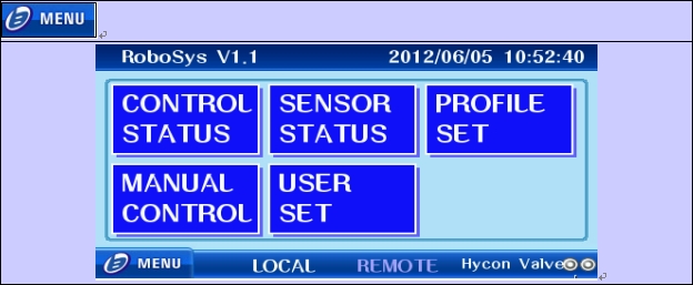
| Step. 10 | Robosys Controller installed on the control panel(4)Check that the menu screen is running when power is supplied to.
|
|
| Step. 11 | go to the menu screen ‘MAUAL CONTROL’ go to. | |
| Step. 12 | Remote Control Pressure Peducing Pilot Valve(6-1) Signal to the solenoid valve installed in the equivalent to check if it works. (open If you press the button OneSolenoid Valve to which the vehicle side piping is connected(9-1)it works, close When the button is pressed, the solenoid valve with piping connected to the atmosphere(9-2)will work.) 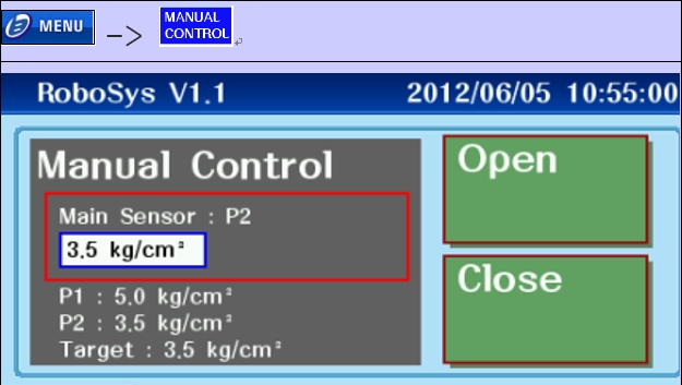 |
|
| Step. 13 | Remote control Pressure Reducing Pilot Valve when solenoid valve is working normally (6-1)Cock Valve of the side piping(3-4)to open. |
|
| <In case of no communication connection> | <When communication is established> | |
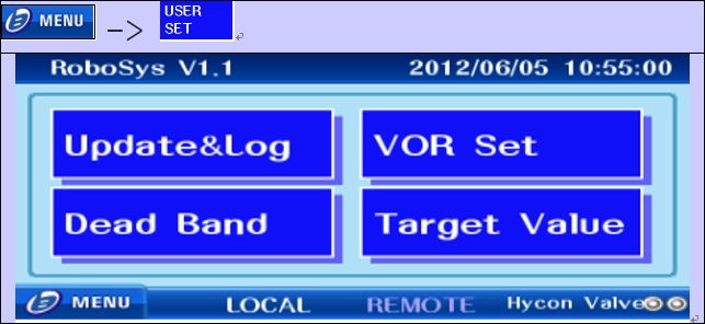
| Step. 14 | go to the menu screen ‘USER SET’go to.
|
at the bottom of the menu screen ‘REMOTE’ check.
|
| Step. 15 | ‘Target Value’ go to.
|
|
| Step. 16 | 2Set the pressure on the car side ‘Confirm’ press the button. | |
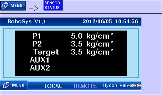
| Step. 17 | go to the menu screen ‘SENSOR STATUS’Go to and check the set pressure value.
|
|
| Step. 18 | Check that the valve is working properly. (2Wait until the differential pressure reaches the set pressure..) |
|
| Step. 19 | 2Slowly fully open the vehicle side gate valve. | |
| Step. 20 | Fudan Ito side(or fire hydrant, acceptor)shut off slowly, make sure it works. | |
| ※ forced open After shutting off the Cock Valve (3-1, 3-2), slowly open the Cock Valve (3-3). (At this time, water comes out from the Cock Valve (3-3), so open it slowly. And when all the water in the main valve cover is drained, no more water should come out. |
||
| ※ force block Open Cock Valve (3-1) and close Cock Valve (3-3). Then slowly shut off the Cock Valve (3-2). |
||
| ※ During valve use(If water is flowing)When resetting the pressure to, Step. One4 → Step. One5 → Step. One6 → Step. One7second run. only, When pressure is reset when pressure is being reduced by a mechanical pressure reducing pilot, Step. 7 → Step. 8 → Step. 9second run. ※ When the valve is not in use, such as for plumbing work, turn off the power to the controller.. |
||
※ – Robosys Robocon Maintenance Guide (Link) –
![]()
![]()
| problem | Solutions |
| One. The problem with the valve itself (damage to the drive, Blockage of the pilot pipe, etc.) |
Replacement of damaged parts and removal of foreign matter from piping |
| 2. Leakage in bypass pipe | Replacing the water valve of the bypass pipe |
| 3. 2When pressure is supplied from another pipe on the car side | Block other connections |
![]()
| problem | Solutions |
| One. Foreign matter in the valve | Removal of foreign matter inside the valve |
| 2. The problem with the valve itself (damage to the drive, Blockage of the pilot pipe, etc.) |
Replacement of damaged parts and removal of foreign matter from piping |
![]()
| problem | Solutions |
| One. The problem with the valve itself (excessive decompression ratio, Pressure setting error, etc.) |
–Reset the pressure so that the decompression ratio is not large (Recommended decompression ratio 3:1) –valve’s Needle class Flow Controller readjustment |
| 2. The problem of pipe design (Install the wrong size valve) |
V-PortInstalled or installed with parallel decompression |
| 3. Problems with other valves on the same line | Before the valve pulsating·rear end valve reset |
Download product file
